Selecting industrial check valves is a small decision with expensive consequences. A failed valve can create reverse flow, water hammer, pump damage, contamination, or an unplanned shutdown. The right choice begins with the fluid, pressure, temperature, pipe size, installation position, and required closing speed.
Industry data supports careful selection. Grand View Research estimates that the global industrial valves market was worth more than USD 75 billion in 2023, with energy, water treatment, chemicals, and manufacturing driving demand. MarketsandMarkets also identifies increasing infrastructure investment and process automation as major growth factors. However, published estimates differ because some reports include actuated valves, while others separate check valves. That difference matters.
Greg Johnson, a recognized valve-industry specialist and former editor of Valve Magazine, has repeatedly emphasized application-based selection. His practical message is clear: “The valve must be selected for the application, not the other way around.” It is a useful warning, even if many purchasing teams still compare price first.
This guide presents 10 practical tips for choosing industrial check valves. It examines swing, lift, wafer, dual-plate, and silent designs. It also considers materials, cracking pressure, flow loss, maintenance access, testing, and relevant standards such as API 594 and API 6D. Look beyond the catalog photograph. A stainless-steel valve may resist corrosion, but it may still fail under unsuitable velocity or repeated surges. No selection method is perfect. Field conditions often expose assumptions that laboratory data misses.
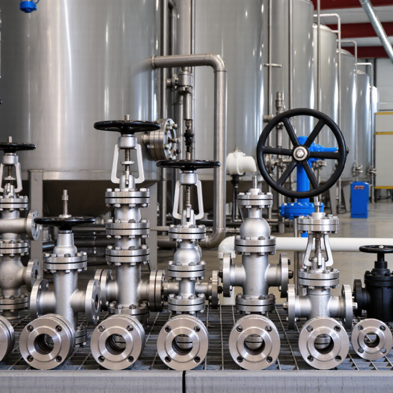
Tip: Start with the real flow range, not only the design flow. Record minimum, normal, and peak flow rates. A valve sized for peak flow may chatter during low-flow operation. In field commissioning, unstable movement often appears before visible damage. Check the fluid temperature, density, viscosity, and solids content. These details change pressure loss and closing behavior. Flow direction also matters, especially in vertical piping. Small mistakes here become expensive later.
Tip: Use Cv to estimate the valve’s flow capacity. A higher Cv usually means lower pressure loss at the same flow. However, maximum capacity is not the only target. Compare the calculated pressure drop with the available pump head. Then check whether the valve operates near its stable range. A spreadsheet may look correct and still mislead you. Real piping includes elbows, reducers, strainers, and elevation changes.
Tip: Treat cracking pressure as a system decision. It is the minimum upstream pressure needed to open the valve. A high cracking pressure may restrict startup flow. A low value may allow reverse flow during pump shutdown. Confirm the pressure available at the valve inlet, especially on long suction lines. Review spring force, disc weight, installation position, and transient conditions. I have seen selections fail because shutdown pressure was ignored. Measure where possible, and question assumptions before final approval.
10 Tips for Choosing Industrial Check Valves
Match Pressure and Temperature Ratings to ASME B16.34 Requirements
Selecting an industrial check valve starts with the actual pressure and temperature envelope. Do not rely on the line size alone. ASME B16.34 provides pressure-temperature ratings based on valve materials, pressure classes, and temperature conditions. A Class 300 valve is not automatically suitable for every service.
Check the maximum operating temperature, design pressure, startup conditions, and shutdown surges. Then compare them with the valve’s rating table and nameplate data. Hot steam can reduce allowable pressure significantly. Cold service can also expose weaknesses in seals, body materials, and bolting. Small details matter. Confirm whether the selected material group matches the process fluid and temperature range.
In field reviews, I often find pressure ratings checked carefully, while thermal cycling receives less attention. That is a mistake worth reconsidering. Repeated heating may loosen connections or accelerate disc wear. Water hammer can create brief pressure spikes beyond normal readings. Include those events in the engineering review, not only the steady-state values. Request material certificates, pressure test records, and traceable documentation from the supplier. I have learned that paperwork can reveal selection gaps before installation. Still, documents are not a substitute for sound design. Verify the complete assembly, including flanges, gaskets, fasteners, and installation orientation, against the same pressure-temperature requirements.
10 Tips for Choosing Industrial Check Valves
Tip 1: Trace the actual flow direction before selecting a valve. Arrow markings must match the pump discharge and process route. A silent check valve may suit clean, steady flow, while a swing check valve can handle larger line sizes with lower pressure loss. Field inspections often find valves installed backward. It happens more than expected.
Tip 2: Match the valve to installation conditions. Vertical piping, limited space, pulsating pumps, and dirty water each change the decision. A lift check valve needs enough pressure to open fully. A wafer-style valve saves space but demands accurate flange alignment. The Hydraulic Institute’s ANSI/HI 9.8 guidance emphasizes hydraulic analysis, especially where pumps and pipeline profiles interact. Do not rely on catalog pressure alone.
Tip 3: Treat water hammer as a design risk, not an afterthought. Rapid closure can create damaging pressure waves, vibration, and repeated flange stress. Closing speed, pipe length, fluid velocity, and elevation all matter. ASCE’s 2021 Infrastructure Report Card rated U.S. drinking water infrastructure C-, showing why preventable failures deserve attention. The EPA’s 7th Drinking Water Infrastructure Needs Survey estimates $625 billion in needs over 20 years. That figure makes small valve decisions less small. Consider non-slam designs, surge vessels, or controlled pump shutdowns. Review calculations with a qualified engineer. Perfect selection is rare; documented assumptions are better.
| No. | Selection Dimension | Typical System Condition | Suitable Check Valve Type | Flow Direction and Installation Guidance | Water Hammer Risk | Key Data to Verify |
|---|---|---|---|---|---|---|
| 1 | Confirm the normal flow direction | One-way flow in a horizontal or vertical pipeline. | Lift, swing, wafer, dual-plate, or axial-flow check valve, selected according to velocity and space. | Install the valve arrow in the actual flow direction. Verify whether the selected design is approved for upward, downward, or horizontal flow. | Low to Medium | Flow direction, line orientation, minimum closing pressure, and manufacturer installation limits. |
| 2 | Match the valve to pipe orientation | Vertical discharge line with upward flow, such as a pump riser. | Spring-assisted inline, axial-flow, or vertical-lift check valve. | Use a valve designed for vertical upward flow. Avoid installing a conventional swing check valve in an orientation that prevents the disc from closing correctly. | Medium | Permitted mounting position, disc weight, spring force, and minimum velocity required for stable operation. |
| 3 | Consider reverse-flow consequences | Reverse flow could damage pumps, compressors, meters, filters, or process equipment. | Fast-closing dual-plate, spring-loaded, nozzle, or axial-flow check valve. | Install as close as practical to the protected equipment when the piping layout and maintenance access allow it. | Medium to High | Allowable reverse-flow rate, closing time, equipment backspin limits, and pressure rating. |
| 4 | Evaluate water hammer exposure | Long water lines, high flow velocity, rapid pump trips, or frequent valve closure. | Non-slam spring-assisted, axial-flow, or controlled-closing check valve. | Choose a design that closes before significant reverse flow develops. A hydraulic transient study may be needed for long or high-head pipelines. | High | Pipe length, fluid velocity, pump trip time, static head, valve closing characteristic, and surge pressure. |
| 5 | Control pressure loss | Continuous pumping, limited pump head, or energy-sensitive water and process systems. | Full-opening swing, axial-flow, or low-loss wafer check valve, subject to service compatibility. | Use the smallest practical pressure-drop design that remains stable at the minimum operating flow. | Low to Medium | Flow rate, valve size, pressure-drop curve, disc position, and available pump differential pressure. |
| 6 | Check minimum and maximum flow | Variable-flow systems with intermittent operation or a wide turndown range. | Spring-loaded inline or axial-flow valve for low-flow stability; swing designs may suit steady higher flow. | Prevent disc flutter by confirming that the operating velocity stays within the valve’s stable range. | Medium | Minimum flow, normal flow, maximum flow, fluid density, fluid viscosity, and allowable cycling frequency. |
| 7 | Account for installation space | Short pipe runs, compact pump skids, or flanged piping with limited face-to-face space. | Wafer dual-plate or wafer lift check valve where the piping standard and service permit. | Confirm clearance for disc movement, bolt installation, removal, inspection, and downstream equipment access. | Low to Medium | Face-to-face length, flange dimensions, bolt clearance, pipe support, and maintenance access. |
| 8 | Select the correct pressure class | Pressurized water, steam, hydrocarbons, chemicals, or high-head pumping systems. | Any suitable check valve type that meets the required pressure-temperature rating. | Install only within the valve’s rated pressure, temperature, and piping-system limits; do not use line size alone as the selection basis. | Medium | Design pressure, operating pressure, shutoff pressure, design temperature, pressure class, and test pressure. |
| 9 | Match materials to the fluid | Potable water, seawater, wastewater, corrosive chemicals, abrasive slurry, or high-temperature service. | Material selection may include coated carbon steel, stainless steel, corrosion-resistant alloys, or lined components. | Verify compatibility of the body, disc, spring, seat, shaft, coating, and elastomers with the complete fluid composition. | Low to Medium | Fluid chemistry, chloride level, solids concentration, pH, temperature, corrosion allowance, and seat material. |
| 10 | Plan for inspection and maintenance | Critical services where leakage, blockage, or valve failure can cause downtime or safety concerns. | Bolted-cover swing, lift, dual-plate, or other serviceable design with accessible internal components. | Provide isolation valves, drain points, lifting space, and safe access where maintenance is required. Follow the applicable piping and valve standards. | Medium | Inspection interval, spare-part availability, seat leakage requirement, isolation arrangement, and applicable design standards. |
10 Tips for Choosing Industrial Check Valves
Corrosion is not a cosmetic issue. The AMPP/NACE IMPACT study estimated global corrosion costs at 3.4% of gross domestic product. That figure makes material selection a financial decision. Tip 1: Identify the fluid, chloride level, temperature, pressure, and flow velocity. Tip 2: Check every wetted component, including the body, disc, spring, seat, and fasteners. Stainless steel may resist one service but fail in another. Duplex alloys can improve resistance, yet they still need proper qualification. Small details matter.
Tip 3: Request material test certificates and traceable heat numbers. Tip 4: Confirm compatibility with sour-service requirements when hydrogen sulfide is present. Tip 5: Examine erosion risk near the hinge, seat, and discharge area. Field inspections often reveal damage that catalog tables miss. That is uncomfortable, but useful. A valve can meet a basic material specification and still perform poorly in real operating cycles.
Tip 6: For pipeline applications, verify the applicable API 6D edition and certification scope. Tip 7: For wafer, lug, and dual-plate designs, check API 594 requirements. Confirm pressure testing, face-to-face dimensions, leakage class, marking, and documentation. Do not accept “API compliant” without supporting records. Tip 8: Match the valve design to installation orientation and reverse-flow risk. Tip 9: Review inspection and maintenance access. Tip 10: Ask for independent verification when service conditions are severe. Standards reduce uncertainty, but they do not replace engineering judgment.
The chart shows approximate pressure ratings at 38 °C for common carbon-steel pressure classes: ASME Class 150, 300, 600, 900, 1500, and 2500. Actual allowable pressure depends on the valve material, temperature, design, and applicable standard. Confirm corrosion resistance, material compatibility, and API 6D or API 594 compliance before purchase.
Choosing industrial check valves starts with leakage evidence, not catalog promises.
ISO 5208:2015 defines six leakage-rate classes, from Rate A, with no visually detectable leakage, to higher permitted rates. API 598 specifies seat and shell test procedures, including pressure, duration, and acceptance limits. Ask for the exact test medium and flow direction. A water test may not predict gas service. Tiny bubbles matter differently in each application. Request a signed test record with temperature, pressure, and test duration.
Face-to-face dimensions can decide whether installation works.
ASME B16.10 provides standardized dimensions for specified valve types and pressure classes. It does not make every check valve interchangeable. Compare nominal size, pressure class, end connection, and actual face-to-face length in millimeters. Leave room for bolt removal and disc inspection. A 10-millimeter mismatch can create piping stress or require an improvised spacer. That is expensive. It is also easy to overlook.
Maintenance needs change with fluid cleanliness and flow direction.
Swing check valves need clearance for disc travel; lift and wafer designs may need careful removal space. The U.S. Department of Energy’s pumping-system sourcebook reports that pumping systems can consume 25% to 50% of electricity in some industrial facilities, making pressure loss worth investigating. Inspect noisy valves and recurring vibration. Seat wear, hinge wear, and reverse-flow damage belong in the maintenance plan.
I have seen a perfect factory test fail in service because debris held the disc open. The uncomfortable lesson: the easiest valve to inspect may outperform the cheapest one.