Blogs | Steelstrong Valves

What Is a Floating Ball Valve and How Does It Work?

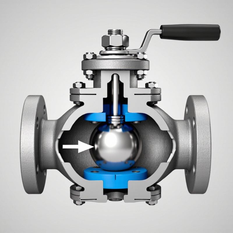
A floating ball valve looks simple from the outside: a compact body, a stem, and a quarter-turn handle. Inside, the ball is not fixed on a lower trunnion. Instead, line pressure pushes it toward the downstream seat, helping create a seal. Turn the stem 90 degrees, and the ball’s bore either lines up with the pipe or blocks the flow. The principle is straightforward. The details matter.

Demand for reliable flow-control equipment is one reason this design appears across water, energy, chemical, and industrial systems. MarketsandMarkets’ 2023 Industrial Valves Market report estimated a global market of $76.2 billion in 2023, with a projected $93.2 billion by 2028. That figure covers industrial valves broadly, not floating ball valves alone. Still, it shows the scale of the equipment sector in which these valves compete. A forecast cannot choose the right valve for a pipeline.

This guide explains the floating ball valve’s parts, sealing action, benefits, and limits. It also distinguishes floating designs from trunnion-mounted valves, whose ball is supported differently. Standards such as API 608 and ISO 17292 provide useful design and testing references, but suitability depends on the valve’s rating, materials, fluid, and operating conditions. Check the manufacturer’s documentation. A small mismatch can matter.
What Is a Floating Ball Valve and How Does It Work?

Definition and Basic Design of a Floating Ball Valve

What Is a Floating Ball Valve and How Does It Work?

A floating ball valve uses a spherical ball that is not fixed to a shaft at both ends. Instead, the ball rests between two seat rings inside the valve body. A stem connects the ball to a handle or actuator and turns it about 90 degrees. When the ball’s bore lines up with the pipe, fluid can pass through. Turn it across the flow, and the solid side blocks the passage.

The ball is called “floating” because it can shift slightly under pressure. In a closed valve, upstream pressure pushes it toward the downstream seat, helping create a seal. The seats also support the ball and limit leakage around it. Small part, large effect. Body shape, seat material, and pressure conditions all influence how well the valve performs. This simple design is common, but it is not automatically right for every line; higher pressure can increase seat load and operating torque.

Tips: Check the valve’s pressure and temperature ratings against the actual service conditions. Before installation, confirm the flow direction if the valve has one, and inspect the seats for damage. A stiff handle is worth investigating, not forcing. Even a sturdy valve can be damaged by rough handling.

Key Components and Their Functions

What Is a Floating Ball Valve and How Does It Work?

Key Components and Their Functions

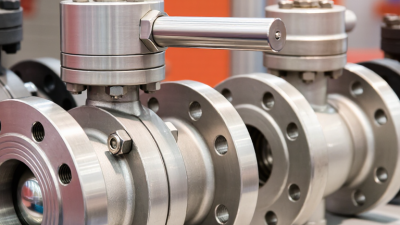
A floating ball valve contains a drilled ball that turns to open or block the flow path. The valve body holds the internal parts and connects to the pipeline. Inside, the ball is not fixed by trunnions; it can shift slightly under pressure. When closed, line pressure pushes it against the downstream seat, helping create a seal. The seats, often made from resilient polymers, cushion the ball and limit leakage.

Small details matter.

The stem links the ball to a handle or actuator and transfers the turning force. A quarter-turn moves the ball between open and closed positions. Stem packing surrounds the stem where it passes through the body, helping prevent fluid from escaping along that route. The body’s end connections and internal seals also need to suit the service conditions, including pressure, temperature, and fluid compatibility.

A mismatch can shorten service life. During inspection, the seats and stem area deserve attention; wear may show up as a harder-to-turn handle or visible leakage. That clue is useful, but not definitive. A qualified inspection is still needed before diagnosing the cause.

How the Ball Moves and Controls Flow

What Is a Floating Ball Valve and How Does It Work?
How the Ball Moves and Controls Flow

A floating ball valve holds a polished ball between two flexible seats. When the stem turns, the ball rotates with it. In the open position, its bore lines up with the pipe, letting fluid pass through. Turn the handle a quarter-turn, and the solid side of the ball faces the flow. Pressure then pushes the ball against the downstream seat, helping form a seal. You can feel the change at the handle.

Flow depends on more than the handle position. The ANSI/ISA 75.01.01 valve-sizing standard relates liquid flow to valve capacity, pressure drop, and fluid density. In simplified form, Q = Cv√(ΔP/SG). Here, Cv describes flow capacity, while ΔP is the pressure difference across the valve. A half-turn does not guarantee half the flow; turbulence, pipe layout, and fluid properties matter. Floating designs are commonly used for shutoff, but sustained throttling can wear seats faster.

Tips: Check the valve’s rated pressure and temperature before installation. For example, ASME B16.34 provides pressure-temperature rating tables for valves. Avoid forcing a stiff handle; debris or excessive pressure may be the cause. A small detail, but often overlooked.

How the Valve Creates a Tight Seal

A floating ball valve creates a tight seal through contact between its ball and seat rings. The ball is held by the stem but can move slightly inside the valve body. When the valve closes, fluid pressure pushes the ball against the downstream seat. That pressure-assisted contact helps block flow. It is a simple mechanism, but small details matter.

The seats are usually made from resilient materials that conform closely to the ball’s smooth surface. In some designs, seat springs maintain contact when pressure is low. A clean, undamaged ball is essential: grit or a fine scratch can create a leak path. During inspection, technicians often check for residue, seat wear, and uneven marks. A caveat: higher pressure can improve sealing, but excessive pressure or unsuitable materials may accelerate wear.

Tips: Verify the valve’s pressure and temperature ratings before use. Keep the line clean during installation, and operate the handle fully rather than leaving it partly open. If leakage appears, do not assume the seat is the only cause; inspect the ball, seals, and installation conditions too. Small signs can be easy to miss.

How a Floating Ball Valve Creates a Tight Seal

In a floating ball valve, upstream pressure pushes the ball downstream against the seat, helping create a seal. This chart shows the idealized pressure force on the projected area of a 50 mm diameter ball, calculated as pressure differential multiplied by projected area. Actual seat loading and sealing performance depend on valve design, materials, and operating conditions.

Common Applications and Operating Limits

A floating ball valve is common in water, compressed-air, and clean-liquid transfer lines. Line pressure pushes its ball against the downstream seat to create a seal. This simple action suits many on-off duties in buildings and process plants. It is less suitable for prolonged throttling, where a partly open ball can erode seats and create unstable flow.

The U.S. Department of Energy’s 2014 pumping-system sourcebook estimates that pumping systems use 25–50% of energy in some industrial facilities. That figure describes whole systems, not savings from one valve. Still, it makes needless throttling worth questioning. Not a magic fix. ASME B16.34 pressure-temperature tables list about 285 psi (19.6 bar) for a Class 150 carbon-steel valve at ambient temperature. That rating changes with material and temperature, and the valve’s own rating may be lower. Check the actual pressure class, fluid temperature, and differential pressure before selection. Hot liquids, abrasive particles, and frequent cycling can shorten seat life; solids may also prevent tight shutoff. A field detail is easy to miss: pressure ratings do not guarantee suitability for every fluid or operating cycle.

What Is a Floating Ball Valve and How Does It Work? - Common Applications and Operating Limits

Topic Description Applications and operating considerations
What it is A quarter-turn valve with a spherical closure element. In a floating design, the ball is not fixed to trunnions; it can move slightly within the valve body. Commonly used for on/off isolation in pipelines and process equipment.
How it works Turning the stem about 90 degrees aligns the ball bore with the pipe to open the valve, or turns the solid side across the flow path to close it. A lever, gearbox, or actuator can provide the rotation, depending on valve size and operating requirements.
Sealing principle When closed, line pressure can push the floating ball against the downstream seat. The seat-to-ball contact forms the primary seal; actual shutoff performance depends on design, materials, and condition. Seat materials and pressure direction should be checked for the service. A specified leakage class or test standard is needed when shutoff performance is critical.
Flow path A full-port valve has a bore close to the connecting pipe’s inside diameter. A reduced-port valve has a smaller bore and may cause a greater pressure drop. Full-port designs suit applications where minimizing flow restriction or allowing pipeline cleaning equipment is important, subject to the system design.
Common applications Isolation of compatible liquids and gases in water treatment, building services, general industrial systems, and process piping. Confirm compatibility with the fluid, including chemical concentration, contaminants, and any solids that could damage seats or interfere with closure.
Throttling suitability Standard floating ball valves are primarily designed for open-or-closed service, rather than prolonged operation at partly open positions. Throttling can create high-velocity jets, vibration, noise, erosion, or seat damage. Use a valve designed and sized for control duty when flow regulation is required.
Pressure limits There is no single pressure limit for all floating ball valves. The allowable pressure depends on the pressure class, size, body and trim materials, seat design, and operating temperature. Use the manufacturer’s pressure-temperature rating for the exact valve configuration and applicable design standard; do not rely on nominal pipe size or class alone.
Temperature limits The body, seals, stem packing, and seats each have temperature constraints. For example, PTFE seats are used across many services, but their permitted range varies by grade, design, and pressure. Check the complete valve rating at the operating temperature. Metal-seat or alternative polymer-seat designs may be needed outside the selected soft-seat material’s limits.
Other operating limits Differential pressure, cycling frequency, flow velocity, fluid cleanliness, and actuator torque can affect performance and service life. Verify the valve’s allowable differential pressure and operating torque, especially for large sizes, high-pressure service, or automated operation.
Selection checklist Specify fluid, size, connection type, pressure and temperature, materials, port type, shutoff requirement, and operating method. Compare the completed specification with the valve’s certified data sheet and applicable piping and safety requirements before installation.

Note: Operating limits are design-specific. Always confirm the pressure-temperature rating and service suitability for the exact valve before use.